Difference between revisions of "RGB-Pi JAMMA Installation"
| Line 1: | Line 1: | ||
| − | |||
| − | |||
'''Steps''' | '''Steps''' | ||
| Line 6: | Line 4: | ||
|- | |- | ||
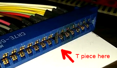
|1. '''DO NOT SKIP THIS STEP'''. Insert the ┳ piece in pin 7 of the female JAMMA harness | |1. '''DO NOT SKIP THIS STEP'''. Insert the ┳ piece in pin 7 of the female JAMMA harness | ||
| + | [[File:Key.png|400px|border]] | ||
|- | |- | ||
|2. With the RGB-Pi board still '''DISCONNECTED''', turn on the cabinet and adjust the voltage in pin 3 to 5.25v | |2. With the RGB-Pi board still '''DISCONNECTED''', turn on the cabinet and adjust the voltage in pin 3 to 5.25v | ||
| Line 12: | Line 11: | ||
|- | |- | ||
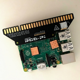
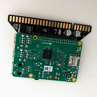
|4. Connect the RGB-Pi board to the Raspberry with the JAMMA connector facing to the outside of the Raspberry Pi | |4. Connect the RGB-Pi board to the Raspberry with the JAMMA connector facing to the outside of the Raspberry Pi | ||
| + | [[File:jamma_1.jpg|320px|border]][[File:jamma_2.jpg|320px|border]] | ||
|- | |- | ||
|5. Put a heatsink on the golden part indicated with the heat symbol (you can use regular Raspberry heatsinks) | |5. Put a heatsink on the golden part indicated with the heat symbol (you can use regular Raspberry heatsinks) | ||
Revision as of 14:17, 2 May 2020
Steps
| 1. DO NOT SKIP THIS STEP. Insert the ┳ piece in pin 7 of the female JAMMA harness |
| 2. With the RGB-Pi board still DISCONNECTED, turn on the cabinet and adjust the voltage in pin 3 to 5.25v |
| 3. If you have an electronic coin acceptor, check that it is not sending any voltage through the pin 16 or T (mechanical coin acceptor users can skip this step) |
| 4. Connect the RGB-Pi board to the Raspberry with the JAMMA connector facing to the outside of the Raspberry Pi |
| 5. Put a heatsink on the golden part indicated with the heat symbol (you can use regular Raspberry heatsinks) |
| 6. Connect the JAMMA connector to the arcade cabinet. DO NOT PLUG ANY USB POWER ADAPTER TO THE RASPBERRY PI |
| 7. That's all! For instructions on how to install RGB-Pi OS, please visit the corresponding section in this wiki. |
JAMMA RGB-Pi Pinout Serie4
   JAMMA / MVS
   ┏━━━━━━━━━━━━━━━━━┳━━━━━━━━━━━━━━━━━┓
   ┃GND             A┃1             GND┃
   ┃GND             B┃2             GND┃
   ┃+5V             C┃3             +5v┃
   ┃+5v             D┃4             +5v┃
   ┃                E┃5                ┃
   ┃+12v            F┃6            +12v┃
   ┃Key             H┃7             Key┃
   ┃                J┃8                ┃
   ┃                K┃9                ┃
   ┃Speaker - or L  L┃10 Speaker + or R┃
   ┃P1 Button7      M┃11               ┃
   ┃Video GREEN     N┃12       VideoRED┃
   ┃Video SYNC      P┃13      VideoBLUE┃
   ┃P2 Button 7     R┃14       VideoGND┃
   ┃                S┃15     Button7 P1┃
   ┃P2 Coin         T┃16        Coin P1┃
   ┃P2 Start        U┃17       Start P1┃
   ┃P2 Up           V┃18          Up P1┃
   ┃P2 Down         W┃19        Down P1┃
   ┃P2 Left         X┃20        Left P1┃
   ┃P2 Right        Y┃21       Right P1┃
   ┃P2 Button1      Z┃22     Button1 P1┃
   ┃P2 Button2      a┃23     Button2 P1┃
   ┃P2 Button3      b┃24     Button3 P1┃
   ┃P2 Button4      c┃25     Button4 P1┃
   ┃P2 Button5      d┃26     Button5 P1┃
   ┃GND/P2 Button6  e┃27 Button6 P1/GND┃
   ┃GND             f┃28            GND┃
   ┗━━━━━━━━━━━━━━━━━┻━━━━━━━━━━━━━━━━━┛
   *Pins 10 & L change depending on the position of the stereo/mono switch. For mono use + - and for stereo use R & L and any ground.
   *Pins 27 & e are connected to GND by default. To enable the same as the 6th button, cut the jumpers JP1 & JP2 on the board.
   Kick
   ┏━━━━━━━━━━━━━━━━━┳━━━━━━━━━━━━━━━━━┓
   ┃P2 Button4      4┃6      Button6 P1┃
   ┃P2 Button5      5┃5      Button5 P1┃
   ┃P2 Button6      6┃4      Button4 P1┃
   ┗━━━━━━━━━━━━━━━━━┻━━━━━━━━━━━━━━━━━┛
   *Take the ground from any pin of the harness


