Difference between revisions of "RGB-Pi JAMMA Installation"
| Line 1: | Line 1: | ||
Available in English and Spanish / *Disponible en Ingles y Español* | Available in English and Spanish / *Disponible en Ingles y Español* | ||
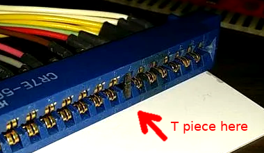
| − | [[File:Key.png|400px|thumb|DON'T SKIP THIS STEP | + | [[File:Key.png|400px|thumb|DON'T SKIP THIS STEP, put on H7 and press hard]] |
'''JAMMA RGB-Pi Pinout''' | '''JAMMA RGB-Pi Pinout''' | ||
Revision as of 21:59, 15 March 2020
Available in English and Spanish / *Disponible en Ingles y Español*
JAMMA RGB-Pi Pinout
   JAMMA / MVS
   ┏━━━━━━━━━━━━━━━━━┳━━━━━━━━━━━━━━━━━┓
   ┃GND             A┃1             GND┃
   ┃GND             B┃2             GND┃
   ┃+5V             C┃3             +5v┃
   ┃+5v             D┃4             +5v┃
   ┃                E┃5                ┃
   ┃+12v            F┃6            +12v┃
   ┃Key             H┃7             Key┃
   ┃                J┃8                ┃
   ┃                K┃9                ┃
   ┃Speaker - or L  L┃10 Speaker + or R┃
   ┃P1 Button7      M┃11               ┃
   ┃Video GREEN     N┃12       VideoRED┃
   ┃Video SYNC      P┃13      VideoBLUE┃
   ┃P2 Button 7     R┃14       VideoGND┃
   ┃P2 Button 8     S┃15     Button8 P1┃
   ┃P2 Coin         T┃16        Coin P1┃
   ┃P2 Start        U┃17       Start P1┃
   ┃P2 Up           V┃18          Up P1┃
   ┃P2 Down         W┃19        Down P1┃
   ┃P2 Left         X┃20        Left P1┃
   ┃P2 Right        Y┃21       Right P1┃
   ┃P2 Button1      Z┃22     Button1 P1┃
   ┃P2 Button2      a┃23     Button2 P1┃
   ┃P2 Button3      b┃24     Button3 P1┃
   ┃P2 Button4      c┃25     Button4 P1┃
   ┃P2 Button5      d┃26     Button5 P1┃
   ┃GND/P2 Button6  e┃27 Button6 P1/GND┃
   ┃GND             f┃28            GND┃
   ┗━━━━━━━━━━━━━━━━━┻━━━━━━━━━━━━━━━━━┛
   *Pins 10 & L changes depend the switch for stereo or mono output, mono use + - indications and stereo use R & L and common ground.
   *Pins 27 & e are plugged to GND by defaut to enable the sixth button cut the jumpers JP1 & JP2 on the board.
   *Los pines 10 y L cambian dependiendo de la posición del switch si está en mono o estéreo, para mono usar las indicaciones + - y para estéreo R y L y una masa común.
   *Los pines 27 y e están conectados a masa por defecto, para habilitarlos como botón sexto bot'on corte los jumpers JP1 y JP2 en la placa.
   Kick
   ┏━━━━━━━━━━━━━━━━━┳━━━━━━━━━━━━━━━━━┓
   ┃P2 Button5   P2B5┃P1B5   Button5 P1┃
   ┃P2 Button6   P2B6┃P1B6   Button6 P1┃
   ┗━━━━━━━━━━━━━━━━━┻━━━━━━━━━━━━━━━━━┛
   *Take the ground from any pin of the harness
   *Coger la masa de cualquier otro pin del jamma.
JAMMA RGB-Pi installation instructions
| Steps: |
| 1. DON'T SKIP THIS STEP, Put one of the ┳ pieces in pin 7 of the female jamma harness |
| 2. WITHOUT THE RGB-Pi CONNECTED turn on the machine and adjust the voltage in pin 3 to 5.25v |
| 3. If you have an electronic coin purse, check that it does not send voltage through the insert coin pin, mechanical coin purse skip this step. |
| 4. Plug the pcb into the raspberry with the jamma connector facing out |
| 5. Put a heatsink on the golden part indicated with the heat (same model as for Pi) |
| 6. Download the latest version of the operating system from rgb-pi.com |
| 7. Format one 8GB or biggest microSD in Fat32 |
| 8. Download Etcher from etcher.io to record the image in the SD |
| 9. Record the image WITHOUT DECOMPRESSING in the SD and EXTRACT WITH SAFETY |
| 10. Put the SD in the Pi and connect the jamma plate WITH THE MACHINE and WITHOUT POWERING THE Pi BY THE MICRO USB |
JAMMA RGB-Pi instrucciones de instalación
| Pasos: |
| 1. NO SALTARSE ESTE PASO, Ponga una de las piezas ┳ en el pin 7 del conector jamma hembra |
| 2. SIN EL RGB-Pi CONECTADO encienda la maquina y ajuste la tension en el pin 3 a 5.25v |
| 3. Si tienes monedero electrónico compruebe que no envía voltaje por el pin del insert coin, monederos mecánicos saltarse este paso. |
| 4. Conecte el pcb en la raspberry con el conector jamma hacia afuera |
| 5. Poner un disipador por la parte dorada indicada con el símbolo de calor (mismo modelo que para la Pi) |
| 6. Descargar la última versión del sistema operativo desde rgb-pi.com |
| 7. Formatear una microSD de 8GB o superior en Fat32 |
| 8. Descargar Etcher de etcher.io para grabar la imagen en la SD |
| 9. Grabar la imagen SIN DESCOMPRIMIR en la SD y EXTRAER CON SEGURIDAD |
| 10. Poner la SD en la Pi y conectar la placa jamma CON LA MÁQUINA APAGADA y SIN ALIMENTAR LA Pi POR EL MICRO USB |
